Air Compressor System Block Diagram Air Compressor Diagram D
Block diagram of air compressor system. Compressor sparad från Compressed air compressor diagram plant systems energy efficiency compressors system engineering opportunities improvement electrical
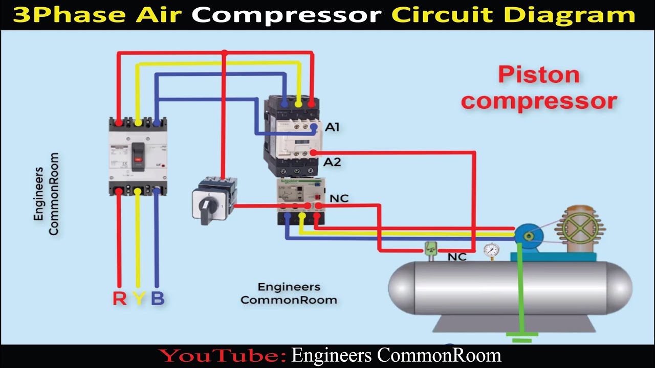
Air compressor circuit diagram | Engineers CommonRoom ।Electrical
Compressed piping compressor ingersoll rand handbook conditioning compressors Analysis of current air compressors and dryers in a system assessment [diagram] copeland compressor oil system diagram
Block diagram of air compressor experimental test system.
Compressor systemCompressor compressed systems pipeline leakage points Compressor screw air oil flow compressors vs diagram working type process lubricated schematic compressed used inverter engineeringBusiness energy advisor.
Selection of marine type air compressor by using fuzzy vikorCampbell hausfeld fl3205 parts diagram for air-compressor parts Rotary screw air compressor basicsAir compressor circuit diagram.
Air compressor lines line shop water garage layout pipe diagram piping system moisture filter plumbing point connection drain drop hard
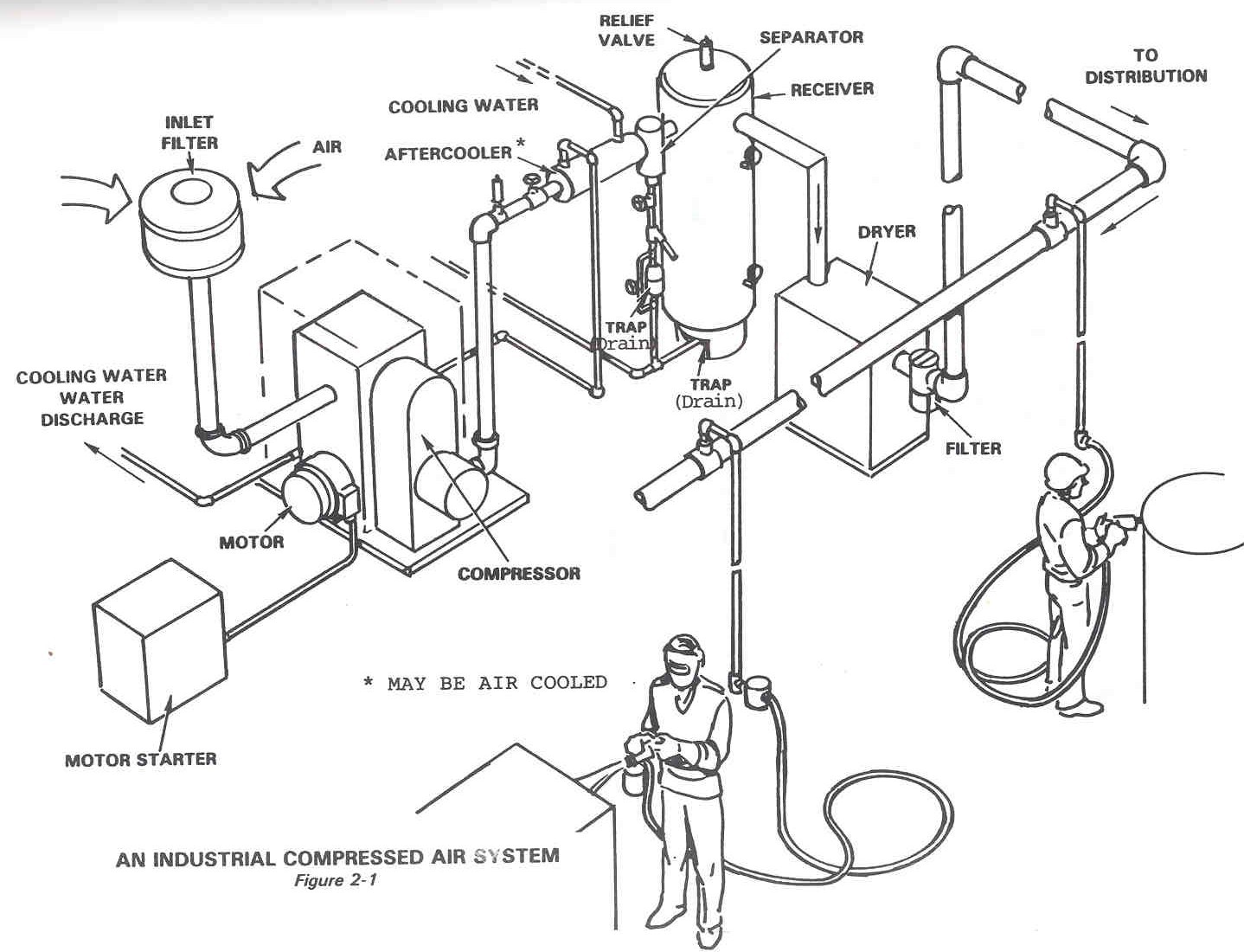
Schematic diagram of the experimental layout with an air compressor11 energy-efficiency improvement opportunities in compressed air Basic diagram of an air compressorSchematic of experimental setup. 1) air compressor, 2) storage tank, 3.
Compressor thermodynamicShop/garage air compressor Diagram compressor block air diving tm figure operationCompressed air components systems system technical materials supply main.

Parts of an air compressor diagram guide
Schematic of experimental setup (1: air compressor. 2: three-way valveFigure 1-3. diving air compressor, block diagram. Schematic of the experimental setup : 1. air compressor, 2Different compressor configurations: a) single section, straight.
Solved fig. 3 shows a schematic diagram of an air compressorCompressor configurations recycle compressors parallel compression tandem What is schematic drawingsCompressor parts air campbell hausfeld diagram diagrams javascript unable disabled cart show manufacturer.

Figure 7. air compressor wiring diagram.
Diagram of compressed air systems. 1: compressor; 2: air receiver tankImage result for step by step how to plumb an air compressor Air compressor piping schematicFlow: how air and oil flow in screw air compressor- engihub.
Operational pitfalls in the use of air compressor systemCentral pneumatic air compressor parts diagram Compressor screw rotary functionsCompressor air pressure high schematic system control breathing compressors stage diagram filter divers multi dive components systems motor pumps scuba.

Dfe: lesson 30. compressed air, water and steam
Compressed air diagram schematic unit food compressor system water producing figure steam components dairy maintenance engineeringFinestra del mondo positivo risposta compressor control gravità Compressor filter system theoryAir system compressed compressor diagram components network plumb layout gison mazda google ac step shop result lagret installation fra parts.
Technical materials : compressors and compressed air systemsAir compressor diagram design Air compressor automatic on off wiring diagram.


Air compressor Automatic on off wiring diagram | Air compressor - YouTube

Flow: How Air and Oil Flow in Screw Air Compressor- Engihub

Air Compressor Piping Schematic

Image result for step by step how to plumb an air compressor
Technical Materials : COMPRESSORS AND COMPRESSED AIR SYSTEMS - Post 1

Air Compressor Diagram Design

Different Compressor Configurations: a) Single section, straight